Circuit cutting
Circuit cutting is a technique to increase the size of circuits that can run on quantum hardware, at the cost of an additional sampling overhead. This addon implements this technique, in which a handful of gates, wires, or both are cut, resulting in smaller circuits that are better suited for execution on hardware. These smaller circuits are then executed, and the results of the original circuit are reconstructed through classical post-processing. However, the trade-off is that the overall number of shots must increase by a factor that is dependent on the number and type of cuts made (known as the sampling overhead). Circuit cutting can also be used to engineer gates between distant qubits which would otherwise require a large SWAP overhead.
Important terms
-
Subcircuits: The set of circuits resulting from cutting gates in a
QuantumCircuitand then separating the disconnected qubit subsets into smaller circuits. These circuits containSingleQubitQPDGates and are used to instantiate each subexperiment. -
Subexperiment: A term used to describe the unique circuit samples associated with a subcircuit, which are sent to a QPU for execution.
Install the circuit cutting package
There are three ways to install the circuit cutting package: PyPI, building from source, and running within a containerized environment. It is recommended to install these packages in a virtual environment to ensure separation between package dependencies.
Install from PyPI
The most straightforward way to install the qiskit-addon-cutting package is with PyPI:
pip install qiskit-addon-cuttingInstall from source
Click here to read how to install this package manually.
Click here to read how to install this package manually.
To contribute to this package or to install it manually, first clone the repository:
git clone git@github.com:Qiskit/qiskit-addon-cutting.gitand install the package with pip. To run the tutorials found in the package repository, install the notebook dependencies as well. Install the dev dependencies if you plan on developing in the repository.
pip install tox notebook -e '.[notebook-dependencies,dev]'Use within Docker
The dockerfile included in the addon repository can be used to build a Docker image. The included compose.yaml file allows you to use the Docker image with the following commands.
Click here to read how to use this package within Docker.
Click here to read how to use this package within Docker.
git clone git@github.com:Qiskit/qiskit-addon-cutting.git
cd qiskit-addon-cutting
docker compose build
docker compose upIf you are using podman and podman-compose instead of docker, the commands are:
podman machine start
podman-compose --podman-pull-args short-name-mode="permissive" build
podman-compose up
Once the container is running, you should see a message similar to:
notebook_1  |     To access the server, open this file in a browser:
notebook_1  |         file:///home/$USERNAME/.local/share/jupyter/runtime/jpserver-7-open.html
notebook_1  |     Or copy and paste one of these URLs:
notebook_1  |         http://e4a04564eb39:8888/lab?token=00ed70b5342f79f0a970ee9821c271eeffaf760a7dcd36ec
notebook_1  |      or http://127.0.0.1:8888/lab?token=00ed70b5342f79f0a970ee9821c271eeffaf760a7dcd36ec
The last URL in this message will give you access to the Jupyter notebook interface.
Additionally, the home directory includes a subdirectory named persistent-volume. All work you would like to save should be placed in this directory, as it is the only one that will be saved across different container runs.
Theoretical background
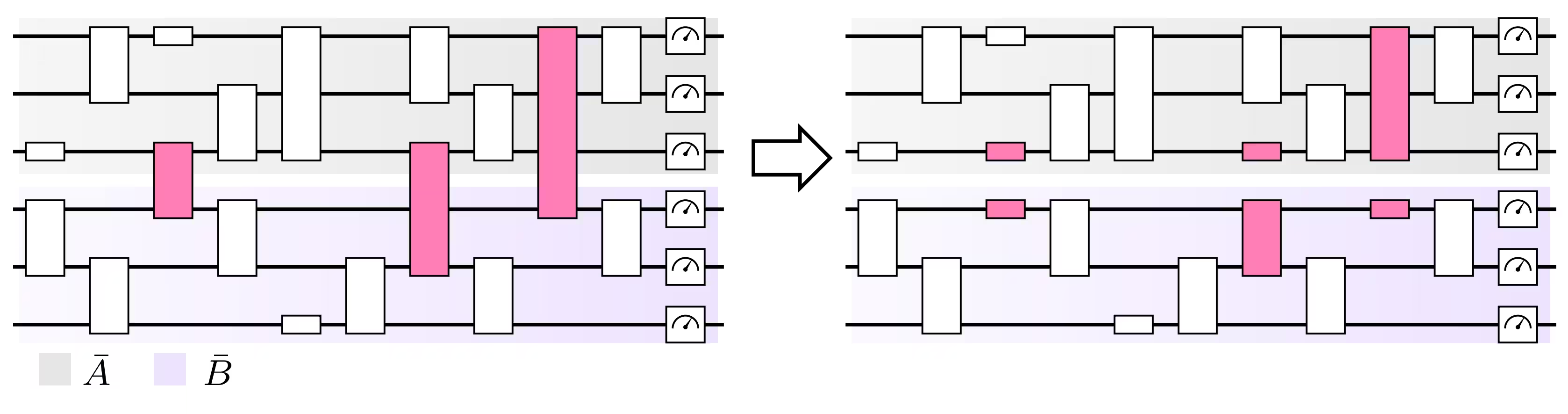
In the circuit cutting process, there are two types of cuts: a gate or "space-like" cut, where a cut goes through a gate operating on two (or more) qubits, and a wire or "time-like" cut, which cuts directly through a qubit wire (essentially a single-qubit identity gate that has been cut into two pieces).
The diagram below depicts an example of cutting gates so that the circuit can be split into two smaller pieces with fewer qubits.
There are three scenarios to consider when preparing a circuit cutting workflow, which center around the availability of classical communication between the circuit executions. The first is where only local operations (LO) are available, while the other two introduce classical communication between executions known as local operations and classical communication (LOCC). The LOCC scenarios are then grouped into either near-time, one-directional communication between circuit executions, or real-time, bi-directional communication (which you might see in a multi-QPU environment).
While circuit cutting can be used to execute quantum circuits larger than what is possible on currently available hardware, it does come at a cost. Because the technique can be framed as a quasi-probability decomposition (QPD) problem, there is an exponential sampling overhead required in order to reconstruct the results. This overhead is the factor by which the overall number of shots must increase in order for the quasi-probability decomposition to result in the same amount of error, , as you would get by executing the original circuit. Each cut gate contributes to this overhead, and the amount of overhead added depends on the type of gate that was cut (more details on the overhead sampling can be found in final appendix of [1]).
For example, a single cut CNOT gate incurs a sampling overhead of 9 [2,6] and a circuit with wire cuts incurs a sampling overhead of when classical communication is not available (the LO scenario). This is reduced to when classical communication becomes available (LOCC scenario) [4]. However, wire cutting with classical communication (LOCC) is not supported by this package.
Formally, the QPD problem of circuit cutting can be expressed as follows:
where is the quantum channel implementing the desired operation, and each is a real coefficient corresponding to a channel, , that is executable on hardware.
The results equivalent to the desired channel are obtained by first generating the coefficients, , then executing subexperiments to obtain the outcomes of the different channels in order to reconstruct the expectation values corresponding to .
A short example: cutting a RZZGate
As a basic explicit example, consider the decomposition of a cut RZZGate (details can be found in [2]). A quantum circuit that contains an RZZGate can be simulated by performing six subexperiments where the RZZGate has been replaced with only single-qubit operations (these are the 's from the equation above). The results of this circuit are reconstructed by combining the results of each subexperiment alongside a set of coefficients (the 's from the equation above), which can be either positive or negative.
For some chosen parameter for the RZZGate, the six subexperiments are as follows:
- With coefficient , do nothing ()
- With coefficient , perform a ZGate on each qubit ()
- With coefficient , perform a projective measurement in the basis on the first qubit and an on the second (). If the result of the measurement is , flip the sign of that outcome's contribution during reconstruction.
- With coefficient , perform a projective measurement in the basis on the first qubit and an on the second (). If the result of the measurement is 1, flip the sign of that outcome's contribution during reconstruction.
- Same as 3. (), but swap the qubits (perform instead).
- Same as 4. (), but swap the qubits (perform instead).
Sampling overhead reference table
The following table provides the sampling overhead factor for a variety of two-qubit instructions, provided that only a single instruction is cut.
| Instructions | KAK decomposition angles | Sampling overhead factor |
|---|---|---|
| CSGate, CSdgGate, CSXGate | ||
| CXGate, CYGate, CZGate, GHGate, ECRGate | ||
| iSwapGate, DCXGate | ||
| SwapGate | ||
| RXXGate, RYYGate, RZZGate, RZXGate | ||
| CRXGate, CRYGate, CRZGate, CPhaseGate | ||
| XXPlusYYGate, XXMinusYYGate | (independent of ) | |
| Move (cut wire in the LO scenario) | N/A |
Next steps
References
[1] Christophe Piveteau, David Sutter, Circuit knitting with classical communication, https://arxiv.org/abs/2205.00016
[2] Kosuke Mitarai, Keisuke Fujii, Constructing a virtual two-qubit gate by sampling single-qubit operations, https://arxiv.org/abs/1909.07534
[3] Kosuke Mitarai, Keisuke Fujii, Overhead for simulating a non-local channel with local channels by quasiprobability sampling, https://arxiv.org/abs/2006.11174
[4] Lukas Brenner, Christophe Piveteau, David Sutter, Optimal wire cutting with classical communication, https://arxiv.org/abs/2302.03366
[5] K. Temme, S. Bravyi, and J. M. Gambetta, Error mitigation for short-depth quantum circuits, https://arxiv.org/abs/1612.02058
[6] Lukas Schmitt, Christophe Piveteau, David Sutter, Cutting circuits with multiple two-qubit unitaries, https://arxiv.org/abs/2312.11638
[7] Jun Zhang, Jiri Vala, K. Birgitta Whaley, Shankar Sastry, A geometric theory of non-local two-qubit operations, https://arxiv.org/abs/quant-ph/0209120